|
|
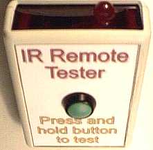
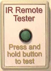
Nigel's Remote Tester.
 The
first stage of this project was deciding on a suitable case, after much
studying I found one in RS Components which is ideal, it has an IR
transparent front available, and includes a space for a 9 volt battery. I
needed a low profile switch for the power, and again a suitable one was
found in the RS Components catalogue. The
first stage of this project was deciding on a suitable case, after much
studying I found one in RS Components which is ideal, it has an IR
transparent front available, and includes a space for a 9 volt battery. I
needed a low profile switch for the power, and again a suitable one was
found in the RS Components catalogue.
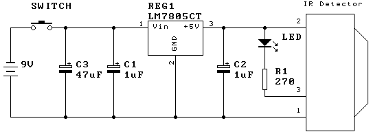
| The
circuit itself is nice and simple, I used components I had to hand, and
selected an IR detector from a Tatung D Series TV for the actual sensor,
with a 7805 IC regulator providing the supply - a 78L05 would be ample,
but I had the 7805 in stock. If you want to use a 78L05, you are welcome
to do so!.
You can get the RS Components parts from their website at http://rswww.com
- they accept orders from non-account holders, but you have to pay
postage, account holders get free postage.
|
Parts List
|
Case |
RS 262-6474 |
|
IR Panel |
RS 262-6496 |
|
Switch |
RS 321-256 |
| REG1 |
LM7805CT |
| LED |
RS 590-171 |
| C1 |
1uF 16v |
| C2 |
1uF 16v |
| C3 |
47uF 16v |
| R1 |
270ohm |
| IR Det. |
Tatung D Series
TFMS5360 |
| Batt. Lead |
RS 489-021 |
|
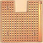
| First
part of building the tester is to cut the Veroboard to size, it needs a
piece 15 strips by 17 holes, and no breaks in the copper strips are
required. A small piece 6 strips by 5 holes requires removing at one
end, this is to provide clearance for the push button switch, the picture
shows this nice and clearly. |

|
 |
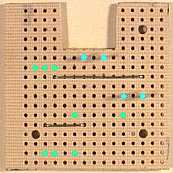
Next
drill the three mounting holes in the board, for these I used a 3/32"
drill, to give a suitable clearance for the screws used to fasten the
board.
|
| Now
it's time to start assembling the board, start by adding the two wire
links, and four Vero pins. The Vero pin locations are shown by the light
blue circles, the light green circles show the holes for the components in
the next step. |
|
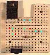 |
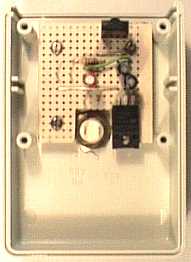
Now
it's time to mount the first components, the 7805 regulator, the 270 ohm
resistor, and the IR detector, these fit in the holes marked light green
in the previous picture. As before the light blue circles signify the Vero
pins, and the light green (and red this time) circles show where the next
components fit - with the red circles being the positive connection of the
capacitors.
|
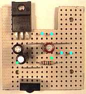
| This
shows the board with the three capacitors fitted, the two close together
at the left are the 1uF, the one on it's own in the middle of the board is
the 47uF. This time the two green dots show the location of an insulated
wire link. |
|
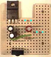 |
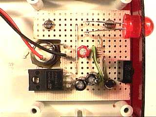
This
is now the finished board, it only requires fitting in the case with three
M2 screws.
|
| Now
it's time to start work on the case, first mark the center of the top, and
drill a half inch hole. You then need to file the hole out until the
switch fits, it has a flange which is larger than the threads, this needs
to fit in the hole. Make sure the switch fits nice and flush. |
|
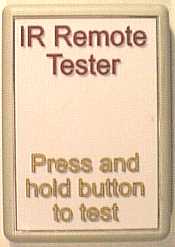 |
Next
stick the front label on, this was designed using Microsoft Publisher
2000, and printed on thin card. This was then laminated and cut out,
laminating provides a nice tough shiny finish, and makes the project look
really professional. I used Super Glue to fasten the label on, although
I've never liked Super Glue it works superbly for this application. You
can download the label as a PDF file, and then print it out, make sure you
have it set to print at 100% to make sure it's the correct size - or feel
free to make your own label.
|
| The
next operation is cutting the front label for the switch, this is easily
done using a sharp knife, just cut a cross through the hole, and then cut
around the hole. Once the hole is clear, mount the switch and tighten the
nut, making sure the terminals are aligned horizontally. |
|
 |
Then
mount the board to the underneath of the top, it's fastened with three
short M2 screws (one hole is obstructed by the 7805), if you have self-tappers
use those, but I found normal threaded screws work perfectly
satisfactorily.
|
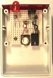
| Now
it's time to mount the LED, first you need to carefully drill a 3/8"
hole in the IR panel 17mm in and 8mm down - be careful, it's quite brittle
and easily broken. Then carefully file this out until the LED is a tight
fit, it doesn't matter if it's a bit loose, we'll secure it with hot melt
glue later. Push the LED into the hole with the long wire towards the left
(looking at the picture), slide the IR panel into the front slot, and bend
the wires down to the two Vero pins, cutting them as required. Then solder
the wires to the pins, a short length of copper wire is also soldered from
the left hand switch connection to the left hand Vero pin at the lower
middle of the board. |
|
 |
The
last electrical operation is to solder the battery connector to the switch
and board. It can be clearly seen here, the red wire goes to the switch
and the black wire to the remaining Vero pin. Tie a knot in the lead about
2 inches from the battery connector, this acts as a flex grip and prevents
the wires being pulled off.
|
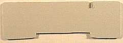
| With
the top of the unit all completed, it's time to start on the bottom part.
First we will use the original front to make a better compartment for the
battery, and give somewhere for the flex grip knot to sit. Cut a long thin
rectangle from the middle of one long edge, this is to clear the latch
from the battery cover, it's also beneficial to taper this edge slightly,
this is also to help clear the latch. Next trim the opposite edge about
1/8 inch, this is to allow the partition to fit inside the case, adjust it
as required. At this side cut a small slot, this is for the battery wires,
it should be small enough for the knot to prevent the wires pulling
through. |
|
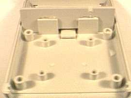 |
Now
using hot melt glue, fasten the partition to the two small existing
partitions, as you can see in the picture the battery flap latch comes through
the portion removed from the partition, and the slot for the battery wires
can be seen at the upper right.
|
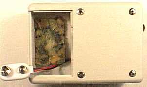
| While
the glue gun is still hot, stick a piece of thin foam rubber in the bottom
of the battery compartment - to stop it rattling. Then use a dab of hot
melt glue to secure the LED to the front panel. The unit is then
completed, and you can screw the bottom on, taking care to feed the
battery wire through the slot, with the knot on the inside. |
|
|