|
Project in progress - an LCD meter, using PIC's.
UPDATE June 2004 - NEW LCD METER PROJECT
![]() This
ongoing project uses an EPROM technology PIC, the 12C672, as an eight bit
analogue to digital converter, it has up to four analogue inputs, but this
design currently uses only two of them.
This
ongoing project uses an EPROM technology PIC, the 12C672, as an eight bit
analogue to digital converter, it has up to four analogue inputs, but this
design currently uses only two of them.
![]() I've
got a couple of different schemes in mind with this project, firstly using
just the 12C672 (the gold coloured UV erasable chip on the right of the
first picture) to feed into a PC serial port, allowing data logging and
plotting of graphs etc. I've written the software in the 12C672 so it can
feed directly to a PC serial port, so it could make a very simple low
cost device. The battery discharge curves on my Misc pages were plotted in a
similar way, using an old hardware A2D connected to the PC parallel port.
I've
got a couple of different schemes in mind with this project, firstly using
just the 12C672 (the gold coloured UV erasable chip on the right of the
first picture) to feed into a PC serial port, allowing data logging and
plotting of graphs etc. I've written the software in the 12C672 so it can
feed directly to a PC serial port, so it could make a very simple low
cost device. The battery discharge curves on my Misc pages were plotted in a
similar way, using an old hardware A2D connected to the PC parallel port.
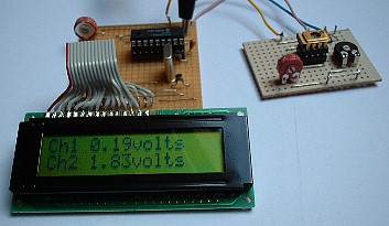
![]() Secondly,
as in the picture, using a 16C84 to feed an LCD display module, the 16C84
accepts the serial data from the 12C672 and displays it on the LCD - you
could use this to simultaneously display upto four different readings, for
example in a dual channel power supply, showing voltage and current for
both channels.
Secondly,
as in the picture, using a 16C84 to feed an LCD display module, the 16C84
accepts the serial data from the 12C672 and displays it on the LCD - you
could use this to simultaneously display upto four different readings, for
example in a dual channel power supply, showing voltage and current for
both channels.
 |
|
|
|
 |
 |
|
 |
|
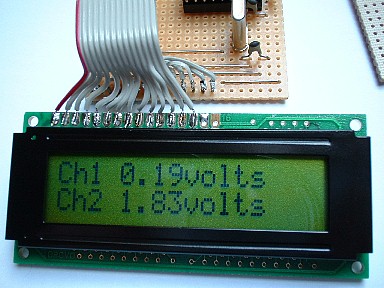
![]() The
software in the 12C672 reads the first input (AD0) and then multiples the
result by 195 to scale the 0-255 result to 0-50000, the resulting
value is then converted into a decimal string, with the lowest two digits
discarded. The decimal numbers are next converted to their ASCII codes, a
decimal point added, and the data sent out as standard 9600baud serial data,
cursor positioning commands are also added to the data stream, and the
various text additions as seen in the pictures. Once AD0 has finished, the
same is done for AD2, and the program then loops back to the start to give
continuous updates.
The
software in the 12C672 reads the first input (AD0) and then multiples the
result by 195 to scale the 0-255 result to 0-50000, the resulting
value is then converted into a decimal string, with the lowest two digits
discarded. The decimal numbers are next converted to their ASCII codes, a
decimal point added, and the data sent out as standard 9600baud serial data,
cursor positioning commands are also added to the data stream, and the
various text additions as seen in the pictures. Once AD0 has finished, the
same is done for AD2, and the program then loops back to the start to give
continuous updates.
![]() The
16C84 reads the data stream, and displays the incoming data, the cursor
positioning commands are striped out and processed separately - command and
display functions are driven separately on these LCD modules. In order to
detect command data, I first send a non-printing character (in this case
0x80) followed by the required data byte - the 16C84 detects the 0x80 and
jumps to a command routine which send the following byte to the display as a
command.
The
16C84 reads the data stream, and displays the incoming data, the cursor
positioning commands are striped out and processed separately - command and
display functions are driven separately on these LCD modules. In order to
detect command data, I first send a non-printing character (in this case
0x80) followed by the required data byte - the 16C84 detects the 0x80 and
jumps to a command routine which send the following byte to the display as a
command.
![]() I'll
be adding the software listings once I've decided exactly what I want to do,
I'm open to any suggestions?.
I'll
be adding the software listings once I've decided exactly what I want to do,
I'm open to any suggestions?.