A Cybot Radio Control PIC RX Board
 Following
on from my original PIC board, I've now started to develop a UHF radio
control link, to provide Cybot with a versatile remote control system.
This page describes the construction of the PIC receiver board, the software and
transmitter board are described on the transmitter
page. Following
on from my original PIC board, I've now started to develop a UHF radio
control link, to provide Cybot with a versatile remote control system.
This page describes the construction of the PIC receiver board, the software and
transmitter board are described on the transmitter
page.
The
PIC receiver board is basically identical to the original one, but the board is six rows
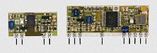
longer, giving room for the UHF receiver module. Again I've used a
crystal (this time a low profile one), but you could use a ceramic
resonator if you wished. The radio module can be ordered from RS
Components at http://rswww.com - the
matching transmitter is part number 376-6539. They cost just over
£20+vat, and work at 433MHz FM, give up to 250 meters range, and
provide up to 9600 baud data rate.
 |
Parts List
| UHF Receiver |
RS 376-6545 |
| Processor |
PIC16F84 |
| Crystal |
4MHz |
| C1, C2 |
10pF |
| C3 |
10uF |
| Connector |
7 way |
| Veroboard |
19 by 24 |
|
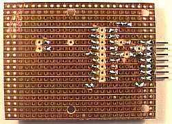 |
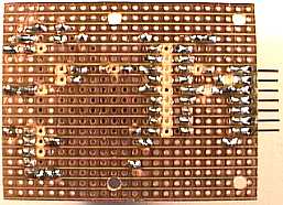
This is a picture of the bottom of the partly constructed board,
the connector, wire links, and IC socket have been fitted. The
breaks in the tracks can be clearly seen. |
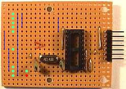
| This shows the top view of the same board, notice the six wire
links!. The green dots show where the next components fit, the 4MHz
crystal, and it's two associated 10pF capacitors. |
 |
 |
This is the top view with the other components fitted, this is identical
to my first board - so you can use these instructions this far to
build the first board. The light green dots show the next component
locations, with the red dot signifying the positive end of C3. The
blue lines show where the five wire links fit. |
| Now we have the extra parts fitted for the radio link, once
again the track breaks can be easily spotted. |
 |
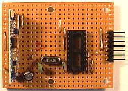 |
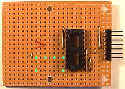
This is a top view of the board with all the components fitted,
the veropin five rows up at the extreme right of the board is for the
aerial to connect to. The wire links don't show up too well on
this picture, there are actually two to the left of the radio
module, these connect the ground pins of the module (pins 2, 7,
11), the long one to the right of the module connects the 5 volt
supply (pins 1 to 15). They can be seen better as the blue lines
in the last picture of the top side of the board. |
|