A Cybot PIC based processor board
by Nigel Goodwin.
 As I've only got up to issue 4 of Cybot so far, I decided to make a small
processor board based on a PIC 16F84, it uses this chip, one 4MHz crystal, two 10pF
capacitors, a small piece of veroboard, and a connector to fit the socket on the
Cybot driver PCB - you can use the one from the test board for this. If you have
a 4MHz ceramic resonator, you could replace the crystal and capacitors with that
- I only used a crystal as I had one to hand. As I've only got up to issue 4 of Cybot so far, I decided to make a small
processor board based on a PIC 16F84, it uses this chip, one 4MHz crystal, two 10pF
capacitors, a small piece of veroboard, and a connector to fit the socket on the
Cybot driver PCB - you can use the one from the test board for this. If you have
a 4MHz ceramic resonator, you could replace the crystal and capacitors with that
- I only used a crystal as I had one to hand.
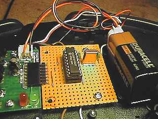 This
is a picture of the board, as I don't yet have the 9 volt battery box, I simply
soldered a PP3 connector to the power socket on the driver board. I wrote
the program in PIC assembler, the tools are freely available from the
MicroChip website for downloading at http://www.microchip.com.
As an initial test I've written a simple routine which tests the different
movements Cybot is capable of, running them all in sequence, for 1 second each,
with a 1 second pause in between. To make programming easy I've written it as a
series of subroutines, and the main program simply calls each as it's required.
The delay routine can be varied, depending on the contents on the W register
when it's called, for each 1 in the W register the routine will wait 1/10th of a
second, giving a maximum delay of 25.5 seconds - if a longer delay is needed,
simply call the routine more than once, or add a longer delay routine -
personally I thought 0.1 second accuracy with a maximum of 25.5 seconds would be
enough. This
is a picture of the board, as I don't yet have the 9 volt battery box, I simply
soldered a PP3 connector to the power socket on the driver board. I wrote
the program in PIC assembler, the tools are freely available from the
MicroChip website for downloading at http://www.microchip.com.
As an initial test I've written a simple routine which tests the different
movements Cybot is capable of, running them all in sequence, for 1 second each,
with a 1 second pause in between. To make programming easy I've written it as a
series of subroutines, and the main program simply calls each as it's required.
The delay routine can be varied, depending on the contents on the W register
when it's called, for each 1 in the W register the routine will wait 1/10th of a
second, giving a maximum delay of 25.5 seconds - if a longer delay is needed,
simply call the routine more than once, or add a longer delay routine -
personally I thought 0.1 second accuracy with a maximum of 25.5 seconds would be
enough. |
 Here is the circuit diagram for the PIC board, as you can see, it's nice and
simple. I used RB0 to RB4 to drive the motors for the simple reason that
they aligned nicely with the connector on the veroboard - one of the nice things
about using a PIC is that you can simply alter your software to make your layout
as easy as possible. I would normally add a decoupling capacitor between GND and
+5V, as close to the chip as possible, but it seems to work fine without it, so
I didn't bother. The routines only use 4 of the available pins to drive
the motors, this leaves the other 9 available as either inputs or outputs, so
this gives plenty of scope for adding sensors to Cybot. Here is the circuit diagram for the PIC board, as you can see, it's nice and
simple. I used RB0 to RB4 to drive the motors for the simple reason that
they aligned nicely with the connector on the veroboard - one of the nice things
about using a PIC is that you can simply alter your software to make your layout
as easy as possible. I would normally add a decoupling capacitor between GND and
+5V, as close to the chip as possible, but it seems to work fine without it, so
I didn't bother. The routines only use 4 of the available pins to drive
the motors, this leaves the other 9 available as either inputs or outputs, so
this gives plenty of scope for adding sensors to Cybot. |
|
I intended adding PWM speed control to my test code, but David A Oram kindly
sent me code he had modified for my board, so I've simply incorporated it into
my original test code. You can download the  original
code, and the PWM code as ZIP files. original
code, and the PWM code as ZIP files.
Here is my
original PIC source for the first test code for the board.
;Cybot test program - Nigel Goodwin Oct 2001


RHFor	equ	01
LHFor	equ	03
RHBak	equ	00
LHBak	equ	02

d1	equ	20
d2	equ	21
del	equ	22

	LIST	p=16F84 , r=dec
	include "P16F84.inc"
	__config H'3FF1'


	org	0000
	goto 	start
	org	0004

; Subroutines

; call 100mS delay number of times in W
Delay	movwf	del
DelLoop	call 	Del100
	decfsz	del, f
	goto	DelLoop
	return

; 100mS delay
Del100	movlw	0x8d
	movwf	d1
Delay_00
	movlw	0xeb
	movwf	d2
Delay_01
	decfsz	d2, f
	goto	Delay_01
	decfsz	d1, f
	goto	Delay_00

			;25 cycles
	movlw	0x08
	movwf	d1
Delay_10
	decfsz	d1, f
	goto	Delay_10

			;1 cycles
	nop

			;4 cycles (including call)
	return


STOP		; stop both motors
	bcf	PORTB,RHBak
	bcf	PORTB,LHBak
	bcf	PORTB,RHFor
	bcf	PORTB,LHFor
	return

FORWARD		; both motors forward
	bcf	PORTB,RHBak
	bcf	PORTB,LHBak
	bsf	PORTB,RHFor
	bsf	PORTB,LHFor
	return

BACKWARD	; both motors backward
	bsf	PORTB,RHBak
	bsf	PORTB,LHBak
	bcf	PORTB,RHFor
	bcf	PORTB,LHFor
	return

LEFT		; RH motor forwards
	bcf	PORTB,RHBak
	bcf	PORTB,LHBak
	bsf	PORTB,RHFor
	bcf	PORTB,LHFor
	return

RIGHT		; LH motor forwards
	bcf	PORTB,RHBak
	bcf	PORTB,LHBak
	bcf	PORTB,RHFor
	bsf	PORTB,LHFor
	return

SPINL		; RH motor forwards, LH motor backwards
	bcf	PORTB,RHBak
	bsf	PORTB,LHBak
	bsf	PORTB,RHFor
	bcf	PORTB,LHFor
	return

SPINR		; LH motor forwards, RH motor backwards
	bsf	PORTB,RHBak
	bcf	PORTB,LHBak
	bcf	PORTB,RHFor
	bsf	PORTB,LHFor
	return

; End of subroutines

; Start of main program

; Define port directions (all as outputs)
start	movlw 	0
	; set bank 1
	bsf	STATUS, RP0
	movwf	TRISB
	movwf	TRISA
	; set bank 0
	bcf	STATUS, RP0


; to call a delay, load the number of 1/10th seconds in W before the call
; the examples below all use 10 (0x0a hex) for a 1 second delay.

MAIN	call	STOP	;ensure all lines are turned off!.

	movlw	0x0a	;set delay to 1 second
	call	Delay	;allow time to place Cybot down
	call	FORWARD

	movlw	0x0a
	call	Delay
	call	STOP

	movlw	0x0a
	call	Delay
	call	BACKWARD

	movlw	0x0a
	call	Delay
	call	STOP

	movlw	0x0a
	call	Delay
	call	RIGHT

	movlw	0x0a
	call	Delay
	call	STOP

	movlw	0x0a
	call	Delay
	call	LEFT

	movlw	0x0a
	call	Delay
	call	STOP

	movlw	0x0a
	call	Delay
	call	SPINL

	movlw	0x0a
	call	Delay
	call	STOP

	movlw	0x0a
	call	Delay
	call	SPINR

	movlw	0x0a
	call	Delay
	goto	MAIN	;loop back to start and run for ever.

	END
|
If you have any queries feel free
to contact me at nigelg@lpilsley.co.uk
or post a question on the CybotBuilder
BBS, if you build one of these boards I would like to hear from you, and
what you have programmed the board to do!.
|

