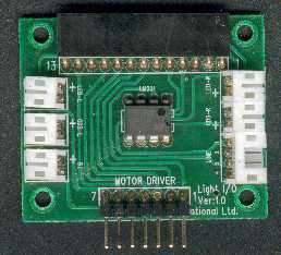
Cybot Light I/O Board
 This
is the circuit diagram of the Light I/O Board. Basically it's just an
interconnection board between the processor and the sensors, however it
has a handful of components fitted, the major one of which is an LM311 comparator
chip. This is used for the line-following mode, so it doesn't do anything
yet, as well as the LM311 it uses a 47K 'pull-up' resistor, the output of
an LM311 is designed so it can be OR'ed with other ones, so it requires
this resistor to make it work. This
is the circuit diagram of the Light I/O Board. Basically it's just an
interconnection board between the processor and the sensors, however it
has a handful of components fitted, the major one of which is an LM311 comparator
chip. This is used for the line-following mode, so it doesn't do anything
yet, as well as the LM311 it uses a 47K 'pull-up' resistor, the output of
an LM311 is designed so it can be OR'ed with other ones, so it requires
this resistor to make it work.
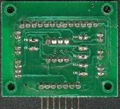
The
only functioning parts at stages 8 & 9 are the resistors R21, R22 and
capacitors C10, C11, these measure the output from the LDR's by measuring
the time it takes for the capacitors to charge up. The LDR's resistance varies with
the amount of light falling on them (the more light, the lower the
resistance), one end connects to 5V and the other through R21 or R22 to
the input of the processor - the capacitors are charged through the LDR's.
It's a standard technique to give a cheap crude A2D conversion, taking the
LH side as an example - you first set pin 4 on the socket as an output,
and set it low, this discharges C10 via the 300 ohm resistor R22, next you
set pin 4 to be an input and you start incrementing a counter while you
keep checking if the pin is high yet. As C10 charges via the LDR a point
will be reached where the input pin reaches it's threshold and goes high,
at this point you stop the counter and it includes a value representing
the analogue value of the LDR. It's simple, but it works pretty well, in
fact analogue joystick ports in PC's work in a similar fashion!.
The
other resistor R20, is simply a current limiter from the 6V rail feeding
the LED's which are part of Cybots antenna in later issues, they are both
connected in series (which means they won't be able to operate
independently), and are fed from the processor via pin 6 of the connector.
|